Level Manager
The vaLevels command opens a dockable Level manager dialog box from which it is possible to create, delete and edit new buildings and levels.
From the Level manager dialog box you can control each level CPlane (construction plane), visibility and its Elevation and Cut Plane values.
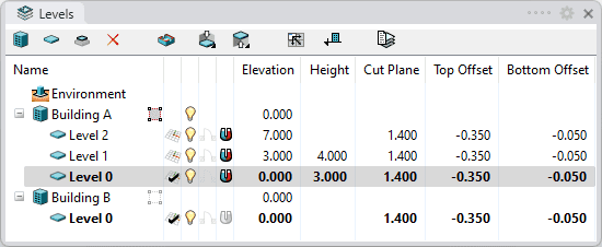
Level Manager dialog box.
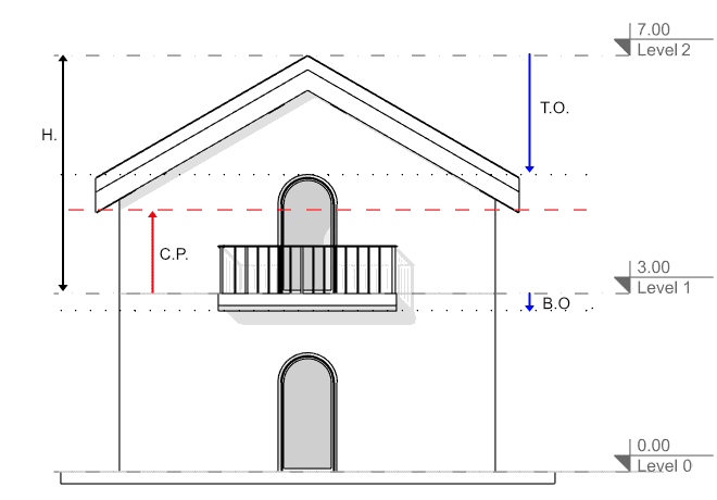
Parameters for Level "1":
- Level 0: Elevation and position of CPlane of "Level 0"
- Level 1: Elevation and position of CPlane of "Level 1" (and top limits of Level 0)
- Level 2: Elevation and position of CPlane of "Level 2" (and top limits of Level 1)
- H.: Height of Level 1
- C.P.: Cut plane elevation of Level 1
- T.O.: Top offset distance of Level 1
- B.O.: Bottom offset distance of Level 1
The Level manager dialog box is divided in two parts:
- Toolbar line
- List of buildings and Levels and their parameters.
1. Toolbar line
New building
 |
Creates new buildings from which you can add levels.
|
New level
 |
Adds a new level to a selected building. More details:
|
New sub-level
 |
Adds a new sub-level to a selected level.
|
Delete
 |
Deletes a specific level, sub-level or building. |
Note:This action does not affect all Rhino and VisualARQ objects which are contained within the deleted level or building. They remain in the same place.
Toggle Cut Plane
 |
This button turns On or Off the Cut Plane of a selected level, in the active viewport. More details:
|
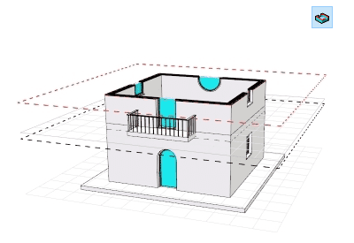
Level 0 and Level 1 view with the Cut Plane on Level 1 On.
Floor plan commands
 This icon shows the following commands in a drop-down menu:
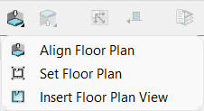
Floor plan view commands.
Align Floor Plan
 |
This button does the following actions in the active viewport for the selected level:
|
Set Floor Plan
 |
This button does the following actions in the active viewport for the selected level:
|
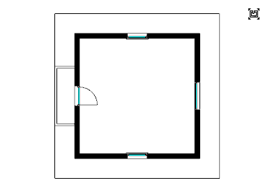
Level 1 after clicking the button Set Plan View To Viewport.
Insert Floor Plan View
 |
This button runs the vaPlanView command to insert a 2D plan view of the selected level, in the model space. |
Ceiling plan commands
 This icon shows the following commands in a drop-down menu:
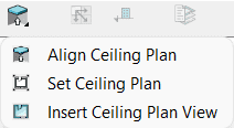
Reflected ceiling plan view commands.
Align Ceiling Plan
 |
This button does the following actions in the active viewport for the selected level:
|
Set Ceiling Plan
 |
This button does the following actions in the active viewport for the selected level:
|
Insert Ceiling Plan View
 |
This button runs the vaPlanView command with the Reflected plan option selected to insert a 2D reflected ceiling plan view of the selected level, in the model space. |
NoteThe ceiling plan shortcut commands in the Level Manager are not available in the VisualARQ 3 version for Rhino 7.
Sync levels in all views
 |
This button toggles the synchronization of the level states in all model viewports.
|
Toggle level's elevation
 |
This button toggles how the the levels elevation is displayed in the Level manager and in the viewports (Front and Side views) elevation references:
|
Level states
 |
This button opens the Level states dialog from which it is possible to save and load different configurations of level states:
|
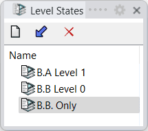
Level States Dialog.
2. List of Buildings and Levels
Name
This column shows the list of the different spatial entities that appear when new buildings or levels are created.
Buildings are ordered alphabetically, and the levels and sub-levels inside each building are ordered according to their elevation.
Environment
 |
|
Building
 |
|
Level
 |
|
Building Boundary
Buildings can have a boundary. The area of this boundary will allow hiding or showing all objects and part of the objects included in this area.
A building boundary can be rectangular or can be defined by a curve. To assign a boundary to a building, click on the boundary icon  next to the building and follow the steps in the command line:
- Rectangular boundary:
- Select first corner of the rectangle
- Select the opposite corner of the rectangle
- Boundary from Curve:
- Select the FromCurves option in the command line
- Select a closed curve in the model. This curve must be a closed convex polyline (which is a polyline that doesn't have any angle higher than 180º) with at most 8 edges.
Once a boundary has been assigned, the building boundary icon changes:
 The building has no boundary.
 The building has a boundary.
The building boundary is represented as Dots linetype and it is displayed projected on the ground plane of the building elevation when selecting a building.
Change building boundary:
- Click on the building boundary icon
 and define a new boundary (as a rectangle or from a curve).
This option is also available from the building context menu.
Remove building boundary:
- Click on the building boundary icon
 and select None option in the command line.
This option is also available from the building context menu.
Extract building boundary:
- Right click on the building name and select the option Extract boundary.
CPlane
 |
|
NoteThe CPlane can't be activated on hidden levels.
On/Off
The level On/Off visibility status shows or hides the objects or parts of the objects situated between the current level Elevation, and the upper level Elevation (taking into account the Top and Bottom offset values).
 The level is visible and you can see objects or parts of the objects on this level.
 The level is not visible, and you cannot see objects or parts of the objects on this level.
Different levels (even if they are not consecutive or they belong to different buildings) can be selected and hidden at once.
NoteHiding a level that has the construction plane on it will switch the construction plane to the level below.
Plan View On/Off
The Plan View displays the 2D representation of any level, in the CPlane (construction plane) of the active viewport. This 2D representation is not editable and only shows the sectioned objects in the selected level, according to the Cut Plane position in that level.
 The selected level 2D representation is visible in the CPlane of the active viewport.
 The selected level 2D representation is not visible in the CPlane of the active
viewport.
NoteThe color of reference plan views is the same as locked objects, which can be changed in Rhino Menu > Tools > Option > Appearance > Colors > Locked objects.
Constraints
This option lets you link objects to levels. When the constraints are enabled on a level, objects located within the level elevation and the elevation of the next level will move when the elevation of the level or the building where they are contained change.
Objects sitting on a level, whose height is the same as the contained level, will change their height according to the new level elevation.
Objects with their Link to level setting unchecked, in the Constraints section ![]() , in the Rhino properties panel
, in the Rhino properties panel  , won't get affected by this level constraints status.
 Level constraints enabled.
 Level constraints disabled.
Set Current Floor
To set a specific level as the current floor in the active viewport, double click on level name. This operation will apply the following changes:
- Put the CPlane onto the selected level
- Turn this level on in case it was hidden.
- Unhide the upper levels of the same building.
Elevation
The Elevation value tells the base height of a building or a level and therefore the position of a Construction plane relative to each one.
- The elevation of a level can be entered by editing this field, or editing the Height field of another level. In that case, the elevations of all affected levels will be recalculated.
- The building elevation value is always measured along the z-axis of the document.
- The elevation of levels can be displayed in relation to the building elevation or in relation to the 0 Z document coordinate, with the Toggle level's elevation button
 .
.
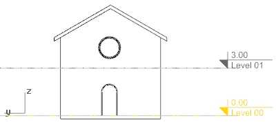
The elevation mark of current level appears highlighted.
Height
The height of a level is determined by the distance between its elevation and the elevation of the upper level. If the level has no level above, it has no specific height.
The height field of a level is editable as long as there is a level above.
Cut Plane height
The Cut Plane determines the elevation of the horizontal section of each floor; i.e., only the objects in that elevation or right under it are included in the representation.
Top offset
The top offset determines the value by which a level's upper limit is increased or decreased when hiding entire levels. This is especially useful when you hide the upper part of a building and want to hide also the upper slab of the last shown level. This value is irrelevant for the top level of a building and only affects viewports that have the Cut Plane off.
Bottom offset
The bottom offset determines the value by which a level's lower limit is increased or decreased when hiding entire levels. This is especially useful when you hide the lower part of a building and want to hide also the lower slab of the last shown level. This value is irrelevant for the bottom level of a building and only affects viewports that have the Cut Plane off.
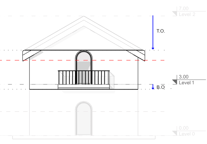
The top (L1 T.O) and bottom (L1 B.O) offsets affect the visibility of Level 1 when hiding the lower and upper levels.
Context menu:
Most of the actions affecting the entities of the Level Manager can be run through the context menu. Doing right-click on any of these entities will display the options available:
- General (for Environment, Building, Level and Sub-level):
- Show all: unhides all buildings and levels in the Level manager and turns the Cut plane off.
- Building:
- Isolate: turns the building visibility on and hides the Environment and other buildings. (This option is only available if the building has a boundary.)
- Show building: turns the building visibility on.
- Set boundary: assigns a new boundary to the building.
- Extract boundary: extracts the building boundary as a polyline in the model space. (This option is only available if the building has a boundary.)
- Remove boundary: removes the boundary from a building. (This option is only available if the building has a boundary.)
- Duplicate: creates a new building with the same number of levels and settings.
- Add Level: creates a new level in the building. The new level is created 3 meters above the last level by default.
- Add Levels...: option to add multiple levels to the building at once. This command opens the Add Multiple Levels dialog, that has the following parameters:
- Number of levels
- Name Format: the "startNumber" text in the syntax %<startNumber>% references the first number in the list of level names.
- Start Number
- Generic Level Parameters: Height, Cut Plane (elevation), and Top and Bottom offsets.
- Direction:
- Up: the levels will be generated upwards, being the Start elevation the lowest.
- Down: the levels will be generated downwards, being the Start elevation the highest.
- Preview: you can see a preview of the list of levels generated according to the indicated parameters.
- Delete: deletes the selected building and all the contained levels.
- Level:
- Isolate: turns the level visibility on and hides the rest of the buildings and levels. The CPlane is automatically set to the isolated level.
- Duplicate: creates a new level with the same settings.
- Add Sub-level: adds a new sub-level.
- Add Sub-levels...: option to add multiple sub-levels to a level at once. This command opens the Add Multiple Levels dialog, that has the same parameters as the one for adding multiple levels to a building (Add Levels...).
- Delete: deletes the selected level and all the contained sub-levels.
- Sub-Level:
- Duplicate: creates a new sub-level with the same settings.
- Add Sub-level: adds a new sub-level to the sub-level.
- Delete: deletes the selected sub-level and all the contained sub-levels.
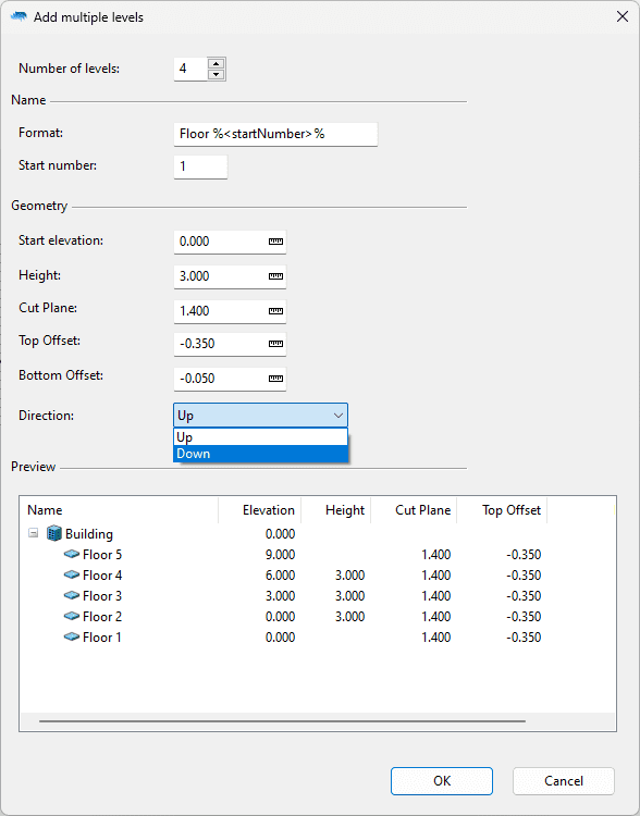
Add multiple levels dialog.
 left click

 The levels elevation is displayed in relation to the building elevation.
 The levels elevation is displayed in relation to the document World origin Z coordinate.
 New state: saves a new level state.
 Load: loads a selected level state from the list into the active viewport.