Guides
- Insert a Guide
- Guide from curves
- Control points
- Insert options and parameters
- Guide Display
- Objects link to guides behaviour
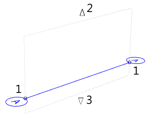
Guides are 2D labeled lines that act as reference points and aid in aligning different elements of the design.
These elements can be either VisualARQ objects as Rhino geometry (polysurfaces, surfaces, curves, etc).
Insert a Guide
After running the vaGuide command, follow the steps from the command line. Press the right mouse button or ENTER to accept and go to the next step.
Steps:
- Specify the guide insert point (in Top or Perspective viewports only).
- Specify the guide end point.
During this command, type L or click on the Label option in the Command line to define the text in the guide label.
NoteWhen running the command again, VisualARQ will remember the text of the last inserted guide and will follow an ordered sequence of text and numbers ((1, 2, 3, 4..., A, B, C, D,... G3, G4, G5, G6..., etc).
Guide: From Curves
Option to create guides from previously drawn curves.
After running the vaGuide > FromCurves command, follow the steps from the command line. Press the right mouse button or ENTER to accept and go to the next step.
Steps:
- Select a Curve or multiple Curves that will be used to generate guides. The curves can be any type or shape of curve, as long as they are flat.
- Specify label name: type a text for the guide label. If multiple curves have been selected, the labels will follow an ordered sequence of text and numbers (1, 2, 3, 4..., A, B, C, D,... G3, G4, G5, G6..., etc).
Control Points 
Guides have the following control points:
- Edge control points. Start and end insertion points.
- Top Control arrow: used to change the vertical range of the guide upwards. (It is not editable in the Top viewport).
- Bottom Control arrow: used to change the vertical range of the guide downwards. (It is not editable in the Top viewport).
Guides also show their planes when their control points are enabled.
Control points on this object are enabled in the same way as on any other object in Rhino. More details.

Insertion Options and Parameters
All the Guide object insertion options and parameters can be edited in the Object Properties
dialog box  or in the VisualARQ Properties section (in Rhino Properties
Panel
  ).
).
General
- Type: guide.
- Name: a field to distinguish a guide from other guides. The name is also used as the text that appears in the guide labels.
- Description: a field for custom notes.
- Enabled: when this option is checked, the objects snapping on that guide will move along with the guide.
- Style: list of Guide styles available in the document.
Geometry
- Text alignment: text alignment inside the guide label. This parameter can be also defined by style. There are three options available:
- Horizontal: the text will be oriented along the X axis.
- Vertical: the text will be oriented along the Y axis.
- Aligned: the text will be oriented following the guide direction.
- Text location: defines in which of the two guide labels the text will appear. This parameter can be also defined by style. There are three options available:
- At both ends: the text and label will appear at both ends of the guide.
- At curve start: the text and label will appear only at the guide start point.
- At curve end: the text and label will appear only at the guide end point.
- Top elevation: this value defines the vertical top range of the guide in elevation views. By default it takes the elevation of the highest level + 4 meters.
- Bottom elevation: this value defines the vertical bottom range of the guide in elevation views. By default it takes the elevation of the lowest level - 1 meter.
Display
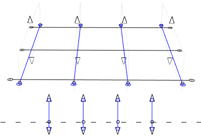
Guides are displayed as 2D labeled lines at their edges on the current construction plane of each viewport.
From the Top and the Perspective viewports, guides are displayed on the horizontal Construction plane (of the current level, or all levels, according to the guide style view settings).
In elevation viewports (Front, Left, Right, etc...), guides are displayed as vertical 2D labeled lines, as long as their path curve is perpendicular to the viewport plane. The guide top and bottom range can be defined by its Top and Bottom elevation properties, or by using the Top and Bottom control arrows.

Guides display in Perspective and in Front viewports.
Objects link to guides behaviour
When objects and geometry are inserted snapping on guides, they get linked to them, according to the valid object types defined by guide styles.
That means that objects aligned on guides or that have one of their edges or points sitting on the guide, will be moved or stretched (only in the case of VisualARQ objects) if those guides are moved.
When guides are created on top of existing objects, these will get linked to guides in the following situations:
- Walls: when the guide is aligned with their path curves or their side bottom edges.
- Curtain walls, beams, stairs and railings: when the guide is aligned with their path curves.
- Slabs and roofs: when the guide is aligned with any of their edges or vertex.
- Column, Furniture, Element, and Annotation objects: when the guide is aligned with their insert point.
- Extrusions, meshes, surfaces and polysurfaces: when the guide is aligned with any of their edges or vertex.
Unlink objects from guides
Objects can be detached from guides from the Constraints section ![]() , in the Rhino properties panel
, in the Rhino properties panel  .
.
NoteWhen guides are moved or stretched from one of their end points along the guide direction, the objects linked to those guides won't get affected, unless part of them are sitting on the guide edges that have been moved.

