Section View
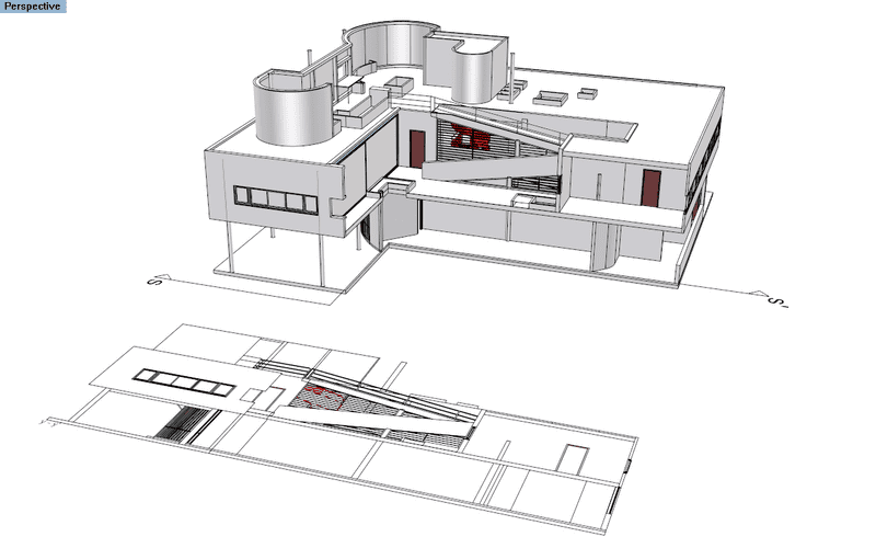
The Section view is a 2D drawing that represents the 3D objects projected on a plane according to a referenced section line in the model.
Insert a Section View
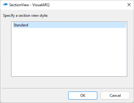
After running the vaSectionView command, the insert dialog box will appear. Follow the steps from the command line. Press the right mouse button or ENTER to accept and go to the next step.

Section View insert dialog
Steps:
- Specify a section view style from the insert dialog box.
- Select the section line.
- Specify an insertion point. Left click anywhere on the screen to insert the section drawing.
This section drawing keeps attached to the section line it was created from, as long as you don't explode it. If the section line is deleted, the section view is also deleted. When you move the section line position, the section drawing updates automatically. The section drawing also maintains the layer properties of the objects it represents.
NoteObjects in layers whose Print Width is set as No Print, won't be generated in the Section View 2D drawing.
Control Points 
The section view drawing has a control point located at its insertion position and a control point to control the position of the reference text.
Control points on this object are enabled in the same way as on any other object in Rhino. More details.
Section View parameters
The following parameters can be defined for each Section View object, after they have been created. They can be edited in the VisualARQ Properties section (in the Rhino Properties Panel ).
).
General
- Type: section view.
- Name: a field to distinguish the section view from other section views.
- Description: a field for custom notes.
- Style: list of section view styles available in the document.
View
- Title: the section view title takes by default the corresponding section line reference text and adds the same text with a " ' ". (i.e. Section reference text = A, Section View title = A-A'). However the section view title can be changed by any other text.
- Section: option to change the section view by selecting a different section line.
- Auto Update: option to enable an automatic update of the Section View when its corresponding section line object is moved or edited.
- Absolute Tolerance: this value determines the precision which the section view is generated with. By default, it takes the Absolute tolerance value of the current document Units (Menu > File > Properties... > Document Properties > Units > Absolute Tolerance), but you can override this value for the section view. (Understanding tolerances)
- Angle Tolerance: sets the angle tolerance when creating geometry in the section view. By default, it takes the value of the current Document Units (File > Properties... > Document Properties > Units > Angle Tolerance), but you can override this value for the section view. (Understanding tolerances)
- Show projection: when this option is unchecked, the section view will only show the sectioned contour and hatch patterns of the sectioned geometry.
Location
- Elevation: section view position in relation to the World Z coordinate.

Model in dynamic section view, section line and section view
Note 1The section view does not show the hidden faces.
Note 2The section view and its corresponding section line are created in the layer that is on when you run the command. Deleting one automatically deletes the other.
Note 3Only objects contained within the section area delimited by its insertion points and its section length points will be displayed in the section view.
