Window Styles
 right click
[left click]
The window style defines the window features. You can define the following parameters in each window style: Name, Attributes, Opening type, Shape and Custom blocks.
Window styles are defined by different components that can be added or deleted at any time: Window Frame, Window Stop, Leaf and Sill.
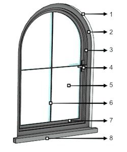
Different parts and components of a window:
 Window Profile
 Window Frame
 Window Stop
 Leaf Handle
 Leaf Glass
- Glass Muntins
 Leaf
Leaf Sill
Sill
After running the vaWindowStyles command, the window Style Manager dialog box will appear. All window styles are created and edited from this dialog.
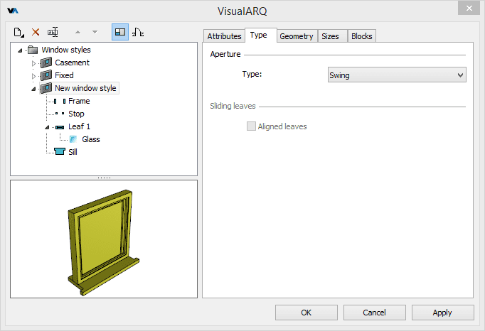
Style Manager dialog box for the window object
New window style:
You can create new styles and duplicate existing ones from the different options in the window Style Manager.
Window styles can be created as regular window styles, or as Grasshopper styles (styles driven by a Grasshopper definition).
When clicking on the New Style... button, select one of the two options available, which will open the corresponding new style wizard:
- Window style: follow the steps of the wizard to define the new window style parameters:
- Name
- Opening type
- Opening profile
- Standard size
- Frame component parameters
- Stop component parameters
- Leaf component parameters
- Sill component parameters
- Custom blocks
- Grasshopper style: follow the steps of the wizard to create a new style from a Grasshopper definition:
- Grasshopper definition
- Global values configuration
- Geometry
- Parameters
Delete a window style:
You can delete window styles from the window Style Manager dialog box. You can only delete those styles that are not being used by any existing window in the model, and that are not the last style inserted in the model.
- Use the vaStyleProperties command, then select a window and press Enter, or
- Right click on
 ,
then select a window and press Enter, or
 - Select a window and open the context menu by pressing the right mouse button for a while then select Window > Style Properties, or
- Press Alt, Shift or Ctrl then double click on a window object.
Edit a window style:
Select the window style or a window component item from the top left panel and edit their different parameters from the tabs that appear in the right panel.
Add a new window component:
- Context menu: right-click on the window style name to open the context menu and select New > "Component item".
- New icon
 : select the window style and click on the New icon from the dialog toolbar. Select "Component item".
Delete components: use the context menu (right-click on the component
you wish to delete and select Delete) or the Delete button ![]() .
.
Attributes
Attributes define the features of a window style and its components for display and print purposes. Check the list of attributes available.
Type
- Aperture Type: VisualARQ can create window styles with six types of aperture:
- Swing: window that is opened to one side on hinges.
- Sliding: window that runs or slides on a rail or slot.
- Hung: window that runs or slides on a vertical rail or slot.
- Awning: window that is opened to one side on horizontal hinges down to up.
- Hopper: window that is opened to one side on horizontal hinges from up to down.
- Fixed: window that can't be opened. (This aperture type is assigned by window leaf).
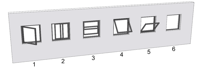
Windows aperture types
- Sliding leaves: option to have the leaves of sliding windows aligned. This option is only enabled for windows with sliding aperture type.
Geometry
Shape Profile: The window shape (or rough opening) is defined by a profile. VisualARQ offers a library with predefined parametric profiles: Rectangular, Circular, 90° Arc, Gothic, etc.
Custom profiles can also be used to define windows using the
vaProfileFromCurve command  , or from the
Profile Manager.
Once the custom profile has been created, it will appear within the list of profiles.
The resulting profile is not parametric, so it can only be used with the dimensions and proportions of the original drawing.
Leaves alignment: position of the leaves in relation to the window's frame: Interior, Center, and Exterior.
Sizes
Each window style has a list of predefined sizes, that can be added, deleted and edited here.
- Add a new size: click on the New button. A new size item will appear in the list. Define its name directly on the list, and edit its dimensions below.
- Delete a size: select the size from the list and click on the Delete button.
- Edit a size: select the size to edit from the list and change its name directly on the list or edit its dimensions below.
The parameters corresponding to the sizes of a window will depend on the type of profile selected.
The sizes can also be specified at any time when inserting the window from the insert dialog box by choosing the Sizes > Other option in the Profile section of this box.
Blocks
Options to create the window Style from blocks
Host
Windows can be inserted in walls, curtain walls, slabs and roofs. Select the valid host type for each window style. The other hosts won't be detected when inserting windows of this style in the model.
Parameters
In this tab you can create custom parameters by style and assign values by style.
These values can be overwritten by object, from the Parameters section  , in the Rhino Properties panel
  .
.
Window components
Frame 
The window styles can only have one frame component.
Geometry
- Width and Depth: dimensions of the frame profile.
- Adjust depth to wall thickness : when this option is enabled, the frame depth takes the host object thickness. When the window is not anchored to any object, the frame depth takes a default value of 200 mm.
Stop 
The window styles can have a window stop.
Geometry
- Width and Depth: dimensions of the stop profile.
Leaves 
The window styles can have one or more leaves. To add a leaf to a window, select the window name on the left side of the dialog box, right-click to open the context menu, and select New > Window Leaf.
Geometry
Options
- Invert opening side: option to change the leaf opening side.
- Fixed leaf: when this option is enabled, the leaf will ignore any aperture and max aperture values assigned to the window object.
Sizes
Leaf width options:
- Auto: the leaf distributes its width equally with the remaining space left by the other leaves.
- Size (%): leaf size defined as a percentage of the total width of the window.
- Width: fixed leaf width dimension.
- Thickness: thickness or depth of the leaf. This value doesn't depend on the leaf size options.
Handle 
The handle component is a nested component of window leaves. Window leaves can have a handle on each side.
Geometry
Type
- Type: there are three handle types available:
- Lever
- Knob
- Embedded
- Escutcheon: it's the piece that joins the handle to the leaf. It can be of 3 different shapes, whose dimensions can't be edited:
- Rectangle
- Circle
- Square
- Orientation: vertical or horizontal. This parameter is only appreciable with rectangular escutcheons.
Position
- Side: determines in which side of the leaf the handle will be located. When a new handle component is added to the same leaf, it is automatically located at the opposite side.
- Vertical alignment: position of the handle (measured from its central external point) in relation to the leaf height. There are three options available:
- Top: this option is measured from the interior edge of the door frame.
- Middle
- Bottom
- Vertical offset: the handle moves in relation to its vertical alignment.
- Horizontal alignment: position of the handle (measured from its central external point) in relation to the leaf width. There are two options available:
- Edge: this option is measured from the interior edge of the door frame, and the edge is determined by the opening side of the leaf.
- Middle
- Horizontal offset: the handle moves in relation to its horizontal alignment
Glass 
Each window leaf contains a glass. When a new leaf is created a glass is included by default. The glass can be removed from the leaf by selecting the Glass component on the left side of the dialog box, right-click to open the context menu, and select Delete. To add a glass to a leaf that has not any, select the Leaf component on the left side of the dialog box, right-click to open the context menu, and select New > Glass.
Glasses can have two different components:
- Glass frame: Frame that holds the glass in a window's leaf. The glass frame properties are the Width and Thickness, which is the same as the leaf thickness and can be edited selecting the leaf component. The frame can be removed from the glass.
- Muntins: The rigid supporting strips between adjacent panes of glass. The muntins properties are the amount of muntins that divide a glass panel and their Width.
Sill 
The window styles can only have a window sill.
Geometry
The window sill properties are:
- Thickness
- Interior/Exterior Extension
- Interior/Exterior Depth.
Custom Blocks
The window styles can be created with 2D and 3D blocks that define their representation in the plan and model views, respectively.
To create a custom window style, assign a profile (which defines the shape of the rough opening on the wall), a
2D block (which defines the plan representation) and a 3D block (which defines the model representation).
Steps:
- Create a custom profile: Draw a planar and closed curve and convert the profile using the
vaProfileFromCurve command
 .
.
Once the custom profile has been created, it will appear at the end of the list of the preset parametric profiles library.
The resulting profile is not parametric, so it can only be used with the dimensions and proportions of the original drawing. - Create the 2D and 3D blocks: Create the 3D model and draw the 2D representation from it. Then create two blocks from them with the Block command (Menu > Edit > Block > Create block definition).
- Create the new window style: Once you have created the profile and the 2D/3D blocks, press the
New style button in the Style Manager dialog box. Use the wizard displayed to assign a custom profile to the style.
Skip the steps where the window style parameters are defined by pressing the Next button until the custom block definition dialog box is displayed.
Select the checkbox that enables the options to use custom blocks for the model and plan views in the Custom Block dialog box. These checkboxes will be only enabled if there is a block created in the document. Once they have been enabled, select the 3D and 2D blocks in the drop-down menu to define the representation of window styles in those views.
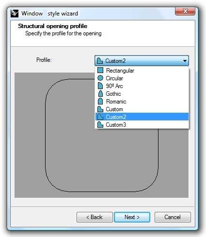
Window creation wizard, Profile selection
Before creating the blocks (2D/3D), make sure that the objects you wish to convert in VisualARQ openings are aligned with the universal X, Y and Z axes (WCS).
Once you have aligned the objects with the WCS, choose the lower center point of your geometry as the insertion point when creating the block.
This will guarantee that the orientation of the opening is correct.
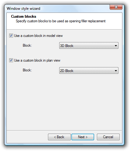
Window creation wizard, block definition
When 3D and 2D blocks are used to define the representation of a custom style, the Sizes, Frame, Window stop and Leaves parameters do not have an effect on the appearance of the style created. Custom styles are NOT parametric: their appearance (size, proportion, level of detail) depends on the block drawing used to define them.
VisualARQ can also create hybrid window styles, replacing only the plan view (with a 2D block) and using the model view of a parametric style or vice versa.
The representation that does not use a block must be defined with style parameters (Sizes, Frame, Window stop and Leaves), as in any standard window style.
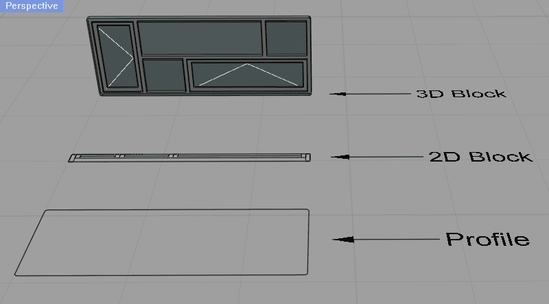
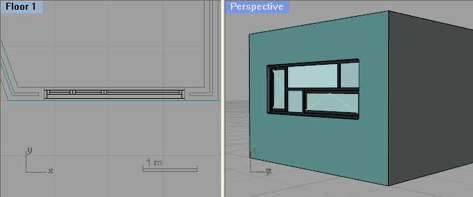
Custom window style, defined from a 3D block, a 2D block and a profile.
