Window
The behavior of windows is identical to that of doors.
Windows can be inserted in a wall, a curtain wall, a slab and a roof object, that act as window host, but they can be also inserted as floating objects, detached from any host object.
In the first case, the window and its host are anchored and the window opening is generated automatically in the object where it is inserted.
Windows can be detached from their hosts by moving them outside of their surface or path limits. In that moment, they can rotate freely in any direction in the 3D model space.
Insert a Window
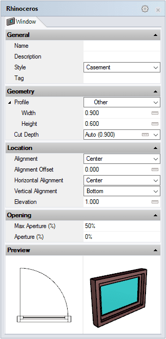
After running the vaWindow command, the window insert dialog box will appear. This dialog box shows a list of all object parameters and a preview in 2D and 3D of the style selected.

Window insert dialog box
The steps required to insert a window depend on the insertion options selected.
Steps:
- Select the Window style you wish to use and define the basic insertion options.
- Select the Window insertion point with a left-click on the desired point in the model. If that point is near to a wall/curtain wall path, the window will be automatically inserted in that wall/curtain wall.
- Specify the window orientation manually with the cursor. (This step is not required when the window has detected a wall or a curtain wall).
- Specify the Opening side by clicking on the desired side of the wall/curtain wall or the window position. This step is not required when you insert a window with the offset option.
You can enter as many windows as you wish and you can cancel the command by pressing ENTER or ESC.
Windows generate an opening in a wall/curtain wall and snap to it as soon at they detect the wall/curtain path.
Window from curve
Windows can be created from curves, which determine their shape profile.
Steps:
- Run the vaWindow command
- Select the Window style you wish to use and define the basic insertion options
- Select the FromCurves option in the command line
- Select a curve (or curves) in the model. This curve must be closed and vertical
The window will be generated at the selected curve and will only be inserted in a host object (wall/curtain wall/slab/roof) if it is close enough.
NoteThe curves selected to create windows don't need to be oriented parallel to the object where they are meant to be inserted. Windows will be inserted and oriented automatically on the host object as soon as they are moved close enough to it.
Control points 

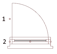
Windows have four control point of two types:
- Opening side: drag this point to the other side of the window or the wall/curtain wall to change the window opening side.
- Left, Center and Right insert point.
To move the window (either in the wall/curtain wall or to a different wall/curtain wall), select it from any point and drag it to the desired location.
To change the opening side of the window, select the control point for the opening side (1) and drag it to the other side of the wall/curtain wall.
Control points on this object are enabled in the same way as on any other object in Rhino. More details.
- Use the vaProperties command, then select a Window and press Enter, or
- Click on
 ,
then select a Window and press Enter, or
 - Select a Window and open the context menu by pressing the right mouse button for a while then select Window > Properties, or,
- Double click on a Window object.
Insertion Options and Parameters
All the window insertion options and parameters can be edited in the Object Properties
dialog box  or in the VisualARQ Properties section (in Rhino Properties
Panel
  ).
).
General
- Type: window.
- Name: a field to distinguish the window from other windows.
- Description: a field for custom notes.
- Style: list of window styles available in the document.
- Tag: reference text that appears in the tag object.
Display
Isocurves and Plan visibility settings for the window display in 3D and plan views.
Geometry
- Window calculated measurements: volume and area.
- Profile: shows a list of predefined profiles stored at the window style. When the profile is set to Other, you can define new values for the profile shape of the selected style.
- Cut depth: value by which the window will generate an opening in the wall. The Auto value is calculated as an appropriate value to ensure the window will generate an opening all the way through the wall.
Location
- Position: change the window insert points from the Point icon
 .
.
- Alignment: windows can be aligned with three methods within the wall/curtain wall thickness

Interior 
Center 
Exterior
- Alignment offset: distance from the window insert point to the wall path.
- Horizontal Alignment: position of the window insert point according to its profile shape.
- Left
- Center
- Right
- Vertical Alignment: window insert point in relation with its vertical distance to the base line of the wall/curtain wall:

Bottom: reference distance between the base line of the wall/curtain wall and the bottom surface of the window. 
Top: reference distance between the base line of the wall/curtain wall and the top surface of the window.
- Elevation: the window elevation in the insert dialog is measured in relation to the baseline of the wall/curtain wall it is inserted in, regardless of its level. After the window has been inserted, its elevation value indicates the window position in the world Z coordinates, regardless of the wall/curtain wall and the level where it is inserted. The default elevation value for windows is 0.
Opening
- Opening side: changes the window opening side from the same side of the wall/curtain wall. The opening side can be also changed from the window Control points.
- Max Aperture (%): defines the maximum aperture the window leaves can reach. The Maximum window aperture is only displayed in Top Viewport when the VisualARQ Plan view mode is enabled, and it is represented with a simple line and an arch.
- Aperture (%): defines how open or closed the window leaves are displayed in perspective and plan views.

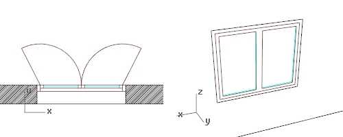
Window aperture example: Max Aperture: 65%, Aperture: 0%
The default aperture value for windows is 50% but you can use values from 0% to 100%.
 left click
[