Wall
- Insert a wall
- Wall: from curves
- Control points
- Insert options and parameters
- Wall joints
- Intersections with other objects
Insert a wall
After running the vaWall command, the wall insert dialog box will appear. This dialog box shows a list of all object parameters and a preview in 2D and 3D of the style selected.
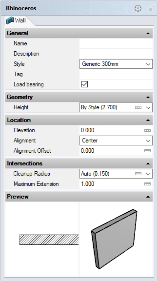
Wall insert dialog box
Steps:
- Select the wall style you wish to use and define the basic insertion options.
- Select the wall start point (insertion point) with a left-click. When you specify the start point, a dynamic dimension will display the length value of the wall being inserted in real-time.
- Left-click again to specify the wall endpoint.
The length and direction of the wall can be specified as follows:
- Entering the coordinates (relative and absolute) in the command line.
- Entering the value to specify the length and/or angle in the command line.
- Manually, by left-clicking the desired point.
Each new wall will be drawn next to the previous one until you press ENTER, ESC or right-click. The command immediately prompts the start point to start drawing the next wall, but it does not link it to the previous wall by default but rather starts drawing it on the new start point selected.
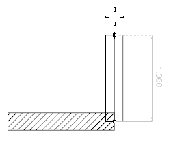
Dimension showing the length of a wall
Wall: From Curves
Option to create walls from previously drawn curves.
When you run the vaWall > FromCurves command, the wall insert dialog box will appear. Follow the steps from the command line. Press the right mouse button out of the wall insert dialog box or hit ENTER to end the command.
Steps:
- Select a Curve or multiple Curves that will be used to generate walls. The curves can be any type or shape, as long as they are flat.
- Select the wall insertion options from the wall
insert dialog box
that will define the wall created from that curve. This
step can be done before or after selecting the curve or curves to
generate walls.
The walls created with this operation behave as all other VisualARQ walls.
Walls created from a polyline generate an individual wall for each polyline segment.
Control Points 
The wall control points are divided into control points and control arrows:
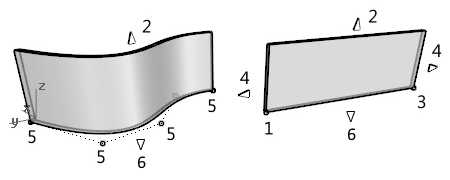
Control points on walls
- Start control point: defines the wall insertion point. Once the wall is inserted, this control point is used to stretch and/or change the wall direction.
- Control arrow upwards (vertical): used to change the height of the wall. (It is not editable in the Top viewport).
- End control point: defines the direction of the wall. It is used to stretch and/or change the wall direction.
- Control arrows (horizontal): used to stretch the wall horizontally from its ends. This control arrow is not available for walls created from curves with a higher degree than 1.
- Wall from curve control points: used to modify the path of walls created from curves.
- Control arrow downwards (vertical): used to change the wall path position. (It is not editable in the Top viewport).
Control points on this object are enabled in the same way as on any other object in Rhino. More details.
- Use the vaProperties command, then select a wall and press Enter, or
- Click on
 ,
then select a wall and press Enter, or
 - Select a wall and open the context menu by pressing the right mouse button for a while then select Wall > Properties, or,
- Double-click on a wall object.
Insertion Options and Parameters
All the wall insertion options and parameters can be edited in the Object Properties
dialog box  or in the VisualARQ Properties section (in the Rhino Properties
Panel
  ).
).
General
- Type: wall.
- Name: a field to distinguish the wall from other walls.
- Description: a field for custom notes.
- Style: list of wall styles available in the document.
- Tag: reference text that appears in the tag object.
- Load bearing: indicates whether the wall performs a structural function or not.
Display
Isocurves and Plan visibility settings for the wall display in 3D and plan views.
Geometry
- Volume, Area, Length, and Thickness. Calculated measurements of the wall. (The area is measured from the vertical surface of the wall, located on its central axis, regardless of the wall alignment).
- Height: even though the Height is a wall style property, you can assign a different value to each wall object in the model.
- Layer Thickness: even though the Layer Thickness is a wall style property, it can be edited individually for each layer of the wall object.
- Layer Top and Bottom Offset: even though the Layer Top and Bottom Offset are wall style properties, they can be edited individually for each layer of the wall object. These parameters change the height of a wall layer from the bottom and from the top.
Location
- Elevation: wall position relative to the World Z coordinate.
- Path Curve: change the wall path from the Curve icon
 .
The wall path can be also edited using its control points or using
the vaWallSetPath command.
- Alignment: there are three options to align the wall, depending on
its position based on the direction of its base curve:

Center 
Right 
Left
- Alignment offset: inserts the wall at a specific distance from the direction of its base curve.
Intersections:
The Intersections between walls (and their layers) are resolved automatically. A wall is extended to a nearby wall by default when it is within its cleanup radius.
-
 The cleanup radius
specifies the maximum distance at which a wall baseline can be from another
wall baseline when joining the two walls.
 -
 The maximum extension specifies the
maximum distance by which one wall extends from its ends points to the point where it intersects with another wall.
Wall joints

When two or more walls join, they calculate their intersection automatically.
There are three types of wall joints:
- None
- Miter
- Butt
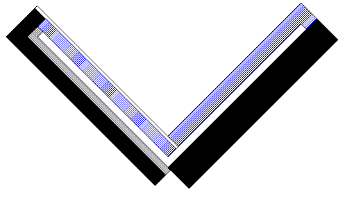
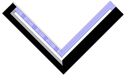
1. Wall Joint: None.
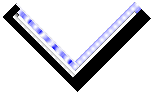
2. Wall Joint: Miter.
3. Wall Joint: Butt.
Editing wall joints:
Wall joints can be edited from the Wall Join icon ![]() , in the Rhino Properties
Panel
, in the Rhino Properties
Panel ![]() , after selecting all walls implied in the intersection.
, after selecting all walls implied in the intersection.
When walls intersect, they take an "auto" joint type that depends on each wall style. If the walls have the same style, the joint type by default is Miter. If the walls have different styles, the joint type by default is Butt.
When three or more walls intersect, the joint resolution depends on the order the walls have been added at the intersection point. The Sort order option, in the Geometry section, allows you to change the order until you find the most appropriate solution.
When two wall layers join, if they have different hatch patterns, a line appears at the joint. If the two layers have the same hatch pattern, no lines appear at the joint.
The intersection of walls created as Grasshopper style is set to Miter by default. It can be changed to None, but the Butt join type is not supported.
Intersections with other objects
Walls interact with other objects and calculate their intersection:
Openings
Doors, windows, and openings generate a void into the wall when these objects are close enough to the wall path.
Columns
Columns always have priority on a wall, and subtract the volume in common from the wall.
Beams
When a wall intersects with a beam tangentially, their tangent edges hide if the wall and the beam have the same section styles.
Slabs and roofs
- 1. Wall and slab/roof layers with the same section attributes hide their intersecting edges, regardless if they are Normal or Core layer types.
- 2. Slab and roof Core layers have priority on wall layers, regardless of their type.
- 3. Wall Core layers have priority on slab and roof Normal layers.
Stairs
- Wall Core layers have priority over a stair and will subtract the volume in common from the stair.
- Wall Normal layers will be cut by the stair.
Create and edit walls
VisualARQ has a toolbar with some options that can be used to create and edit walls in different ways.
 left click
[

 left click
[