Slab
- Insert a Slab
- Slab: from curves
- Slab: from surface
- Control points
- Insert options and parameters
- Intersections with other objects
Slabs are defined by a boundary curve or a planar surface. They can be created as rectangular shapes (by default) or from any existing curve in the model.
Insert a Slab
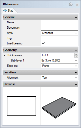
After running the vaSlab command, the slab insert dialog box will appear. This dialog box shows a list of all object parameters and a preview in 2D and 3D of the style selected.
Follow the steps from the command line. Press the right mouse button out of the insert dialog box or hit ENTER to end the command.

Slab insert dialog box
Rectangular Slab
Steps:
- Select the Slab style you wish to use and define the basic insertion options.
- Pick the two opposite corners that will define the slab.
Rectangular slab from three points
Steps:
- Select the Slab style you wish to use and define the basic insertion options.
- Select the 3Point option in the Command line.
- Pick a point in the model as the slab start edge.
- Pick a point in the model as the slab end edge.
- Pick a point in the model as the slab width.
Slab: From Curves
Slabs can be also created from previously drawn curves in the model.
Steps:
- Select the Slab style you wish to use and define the basic insertion options from the Insert Dialog.
- Pick a curve or multiple curves that will be used as the slab's start boundary. These curves must be planar and closed.

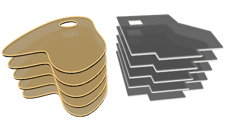
Slabs created with curves and polylines.
Slab: From Surface
Slabs can be also created from existing surfaces in the model.
Steps:
- Select the Slab style you wish to use and define the basic insertion options from the Insert Dialog.
- Pick a surface or multiple surfaces that will be used as the slab boundary. These surfaces must be planar.
Control Points 
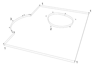
Slabs have as many control points as the original curve they were created from. You can select any of these points and change the slab boundary position.

- Slab boundary control points.
- New slab boundary points from subtracted boundaries.
- New slab boundary points from added boundaries.
Control points on this object are enabled in the same way as on any other object in Rhino. More details.
- Use the vaProperties command, then select a Slab and press Enter, or
- Click on
 ,
then select a Slab and press Enter, or
 - Select a Slab and open the context menu by pressing the right mouse button for a while then select Slab > Properties, or,
- Double-click on a Slab object.
Insertion Options and Parameters
All the slab insertion options and parameters can be edited in the VisualARQ Properties section (in the Rhino Properties
Panel  ).
).
General
- Type: slab.
- Name: a field to distinguish the slab from other slabs.
- Description: a field for custom notes.
- Style: list of slab styles available in the document.
- Tag: reference text that appears in the tag object.
Display
Isocurves and Plan visibility settings for the slab display in 3D and plan views.
Geometry
- Slab calculated measurements: volume, area, and thickness.
- Thicknesses: even though the slab thickness is a property defined by the slab style, it can be edited individually for each layer of a slab object.
- Edge cut:
- Flat
- Plumb (default value)
- Square

Location
- Elevation: slab position relative to the World Z coordinate.
- Alignment: position of the slab relative to its boundary curve. There are three options available:
 Top: the slab is aligned with the boundary curve from its top surface.
 Center: the central horizontal cross section is aligned with the boundary curve.
 Bottom: the slab is aligned with the boundary curve from its bottom surface.
Intersections with other objects
Slabs
When a slab intersects with another slab, they solve their intersection according to these criteria:
- 1. Slab layers with the same section attributes hide their intersecting edges, regardless if they are Normal or Core layer types.
- 2. Slabs with the same layer types solve their intersection according to the order of creation. The first slab subtracts the solid in common with the other slab.
- 3. Slab Core layers have priority on slab Normal layers.

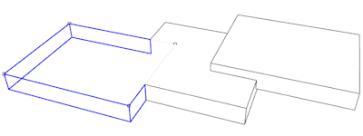
Examples of slab intersections.
Walls
When a slab intersects with a wall, they solve their intersection according to these criteria:
- 1. Wall and slab layers with the same section attributes hide their intersecting edges, regardless if they are Normal or Core layer types.
- 2. Slab Core layers have priority on wall layers, regardless of their type.
- 3. Wall Core layers have priority on slab Normal layers.

Wall-Slab Intersections.
Roofs
When a slab intersects with a roof, they solve their intersection according to these criteria:
- 1. Slab and roof layers with the same section attributes hide their intersecting edges, regardless if they are Normal or Core layer types.
- 2. Roof layers have priority over slab layers of the same type.
- 3. Core layers have priority over Normal layers. (In the example below, the slab has a Core layer, and the roof a Normal layer).

Example of a slab-roof intersection.
Stairs
When a slab intersects with a stair slab, they solve their intersection according to these criteria:
- 1. Slab layers and stair slabs with the same section attributes hide their intersecting edges.
- 2. The stair slab has priority over Normal slab layers.
- 3. Slab Core layers have priority over the stair slab.
Beams
When a slab intersects with a beam tangentially, their tangent edges hide if the slab and the beam have the same section styles.
Edit Slabs
To edit a slab, VisualARQ has a toolbar with some options that can be used to modify the slab shape.
 left click [

 left click
 left click