Railing Styles
 right click
[left click]
right click
[left click]
The railing style defines the railing features. You can define the following parameters in each railing style: Name and Attributes.
Each railing style is defined by the combination of 3 components that can be added or deleted anytime: Rail, Post and Baluster.
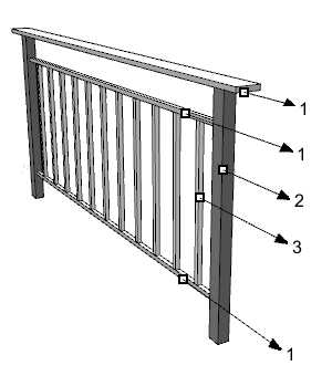
Different parts and components of a railing:
- 1.
 Rail
Rail - 2.
 Post
Post - 3.
 Baluster
You can define the following parameters for each railing style and each component: Name, Attributes, Location, Geometry and Profile.
After running the vaRailingStyles command, the railing Style Manager dialog box will appear. All railing styles are created and edited from this dialog.
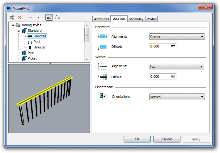
Style Manager dialog box for the railing object
New railing style
You can create new styles and duplicate existing ones from the different options in the railing Style Manager.
Railing styles can be created as regular railing styles, or as Grasshopper styles (styles driven by a Grasshopper definition).
When clicking on the New Style... button, select one of the two options available, which will create a new railing style or open the Grasshopper style wizard:
- Railing style: a new railing style is created with the default parameters.
- Grasshopper style: follow the steps of the wizard to create a new style from a Grasshopper definition:
- Grasshopper definition
- Global values configuration
- Geometry
- Parameters
Delete a railing style:
You can delete railing styles from the Railing Style Manager dialog box. You can only delete those styles that are not being used by any existing railing in the model.
Edit a railing style:
Select the railing style or a railing component item from the top left panel and edit their different parameters from the tabs that appear in the right panel.
Add a new railing component:
- Context menu: right-click on the railing style name to open the context menu and select New > "Component item".
- New icon
 : select the railing style and click on the New icon from the dialog toolbar. Select
"Component item".
: select the railing style and click on the New icon from the dialog toolbar. Select
"Component item".
Delete components: use the context menu (right-click on the component
you wish to delete and select Delete) or the Delete button ![]() .
.
- Use the vaStyleProperties command, then select a railing and press Enter, or
- Right click on
 ,
then select a railing and press Enter, or
,
then select a railing and press Enter, or - Select a railing and open the context menu by pressing the right mouse button for a while then select Railing > Style Properties, or
- Press Alt, Shift or Ctrl then double click on a railing object.
Attributes
Attributes define the features of each railing style and its components for display and print purposes. Check the list of attributes available.
Parameters
In this tab you can create custom parameters by style and assign values by style.
These values can be overwritten by object, from the Parameters section  , in the Rhino Properties panel
  .
.
Railing components
Rail
It is the horizontal component that goes along the base path curve. It can define the handrail or the secondary rails of the railing object. The rail component is defined by the following parameters:
Location
The location of the rail component defines its position in relation with the base path curve and the railing height.
 Horizontal alignment: the rail alignment depends
on the direction of the base curve. It has three different options:
Exterior,
Center and Interior.
Horizontal alignment: the rail alignment depends
on the direction of the base curve. It has three different options:
Exterior,
Center and Interior.  Horizontal offset:
the
horizontal alignment offset inserts the
rail at a specific distance from the base curve.
Horizontal offset:
the
horizontal alignment offset inserts the
rail at a specific distance from the base curve. Vertical alignment:
the vertical alignment
defines the vertical position of the rail component in relation with the total
height of the railing object. It has three different options: Top,
Center and Bottom.
Vertical alignment:
the vertical alignment
defines the vertical position of the rail component in relation with the total
height of the railing object. It has three different options: Top,
Center and Bottom.  Vertical offset: the vertical alignment offset inserts the rail
at a specific distance from the vertical alignment position.
Vertical offset: the vertical alignment offset inserts the rail
at a specific distance from the vertical alignment position. Orientation:
- Aligned: the geometry is generated extruding the rail profile perpendicular to the railing axis direction.
- Vertical: the geometry is generated extruding the rail profile vertically along the railing axis direction.
The sizes can be specified at any time when inserting the railing from the insert dialog box by choosing the Sizes > Other option in the Profile section of this panel.
Geometry:
The geometry parameters of the rail components define them at their ends and at their joints:
Ends:
 Style: options to define the rail edge cut at ends:
- Square
- Plumb

 Margin:
distance between the ends of the railing path curve and the rail ends.
Margin:
distance between the ends of the railing path curve and the rail ends.
Joints
 Planar:
- None
- Break
- Miter

 Non
planar:
Non
planar:
- None
- Break
- Miter
- Flat

Profile
 Profile: the rail shape is defined by a profile and by its size. This list shows the profiles available for the rail component,
including the custom profiles created with the vaProfileFromCurve
Profile: the rail shape is defined by a profile and by its size. This list shows the profiles available for the rail component,
including the custom profiles created with the vaProfileFromCurve
 command, or from the Profile Manager.
 Rotation: angle by which the rail rotate around its axis, taking as the center of rotation the central point of its profile area.
- Sizes: The parameters corresponding to the rail sizes will vary in accordance with the type of profile selected.
Post
The posts are the main vertical component of a railing object. A post is placed at the end and start points of a railing path curve and at each one of the discontinuity points in between. The Post component is defined by the following parameters:
Location
The location of the post component defines its position in relation with the base path curve and the railing height.
 Horizontal alignment:
the post alignment depends
on the direction of the base curve. It has three different options:
Exterior,
Center and Interior.
Horizontal alignment:
the post alignment depends
on the direction of the base curve. It has three different options:
Exterior,
Center and Interior. Horizontal alignment offset:
the offset alignment inserts the post at a specific distance from the base curve.
Horizontal alignment offset:
the offset alignment inserts the post at a specific distance from the base curve.
 Ends margin: distance between the posts and the ends of the
railing base curve.
Ends margin: distance between the posts and the ends of the
railing base curve.
Profile
- Profile: the post shape is defined by a profile and by its size. This list shows the profiles available for the post component,
including the custom profiles created with the vaProfileFromCurve
command, or from the Profile Manager.
- Rotation: angle by which posts rotate around their axis, taking as the center of rotation the central point of their profile area.
- Sizes: The parameters corresponding to the post sizes will vary in accordance with the type of profile selected.
Baluster
The baluster is the secondary vertical component of a railing object.
Location
The location of the baluster component defines its position in relation with the railing base path curve.
- Horizontal alignment:
the baluster alignment depends
on the direction of the base curve. It has three different options:
Interior,
Center and Exterior.
- Horizontal alignment offset:
the offset alignment inserts the
balusters at a specific distance from the base curve.
 Path distance: maximum distance between the central vertical axis
of each baluster along the railing path. This distance might not be exact when the alignment is set to Justify.
Path distance: maximum distance between the central vertical axis
of each baluster along the railing path. This distance might not be exact when the alignment is set to Justify. Path alignment:
distribution of balusters along the railing path. There are four options available:
Path alignment:
distribution of balusters along the railing path. There are four options available:
- Start
- Middle
- End
- Justify
 Path margin: distance between the external faces of the
posts and the nearest baluster face. Posts are located at the ends and at
the discontinuity points of the railing base curve. In railings which do not have posts, the path margin distance is
the one between the first and last balusters, located at the ends of
the railing base curve and at the
discontinuity points.
Path margin: distance between the external faces of the
posts and the nearest baluster face. Posts are located at the ends and at
the discontinuity points of the railing base curve. In railings which do not have posts, the path margin distance is
the one between the first and last balusters, located at the ends of
the railing base curve and at the
discontinuity points.
Geometry
The geometry of the baluster component defines its shape in relation with the railing height.
 Top
margin: distance between the top of the railing and the top surface of the baluster.
Top
margin: distance between the top of the railing and the top surface of the baluster. Bottom
margin: distance between the base line of the railing and the bottom surface of the baluster.
Bottom
margin: distance between the base line of the railing and the bottom surface of the baluster.
Profile
- Profile: the baluster shape is defined by a profile and by its size. This list shows the profiles available for the baluster component,
including the custom profiles created with the vaProfileFromCurve
command, or from the Profile Manager.
- Rotation: angle by which balusters rotate around their axis, taking as the center of rotation the central point of their profile area.
- Sizes: The parameters corresponding to the baluster sizes will vary in accordance with the type of profile selected.
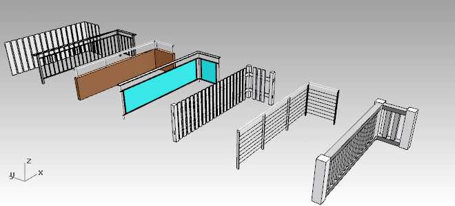
Railing styles samples