Column
 left click
[right click]
Columns can be inserted inside or outside a wall.
When they are inserted in a wall, the column boundary automatically cuts out the wall line crossing it in order to define the intersection between both elements (in the Plan and Perspective views).
Insert a Column
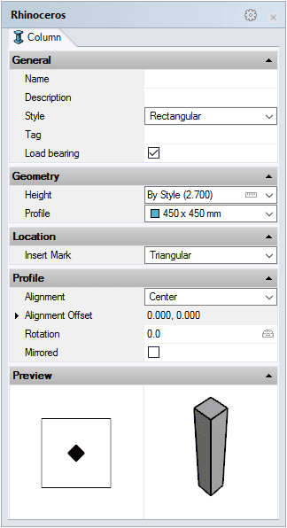
After running the vaColumn command, the column insert dialog box will appear. This dialog box shows a list of all object parameters and a preview in 2D and 3D of the style selected.

Column insert dialog box
Steps:
- Select the Column style you wish to use and define the basic insertion options.
- Select the Column insertion point with a left-click on the desired point.
- Specify the Column orientation manually with the cursor. Click again when the column is on the desired point.
You can enter as many columns as you wish and you can cancel the command by pressing ENTER or ESC.
Control Points 
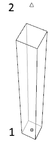
Columns have one control point and one control arrow:
- Insert point: located at the column base, it corresponds to the alignment chosen for the column when it is inserted.
- Vertical extension arrow: it is used to change the height of the column.

Control points on columns
Control points on this object are enabled in the same way as on any other object in Rhino. More details.
- Use the vaProperties command, then select a Column and press Enter, or
- Click on
 ,
then select a Column and press Enter, or
 - Select a Column and open the context menu by pressing the right mouse button for a while then select Column > Properties, or,
- Double click on a Column object.
Insertion Options and Parameters
All the column insertion options and parameters can be edited in the Object Properties
dialog box  or in the VisualARQ Properties section (in Rhino Properties
Panel
  ).
).
General
- Type: column.
- Name: a field to distinguish the column from other columns.
- Description: a field for custom notes.
- Style: list of column styles available in the document.
- Tag: reference text that appears in the tag object.
- Load bearing: indicates whether the column performs a structural function or not.
Display
Isocurves and Plan visibility settings for the column display in 3D and plan views.
Geometry
- Column calculated measurements: volume.
- Height: even though Height is a column style property, you can assign a value that is different to the default height value in the insert dialog box.
- Profile: shows a list of predefined profiles stored at the column style. When the profile is set to Other, you can define new values for the profile shape of the selected style.
Location
- Insert point: change the column insert point from the Point icon
 .
.
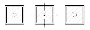
- Insert mark: the mark displayed on the alignment point which indicates the fixed column face. Insert marks are only displayed in the Plan view. Besides the None option you can select one of the following shapes:
- Triangular
- Axes
- Circular

Columns with different types of insert marks
Profile
- Alignment: position of the column insertion point according to its profile shape:
- Top Left, Top Center and Top Right
- Middle Left, Center and Middle Right
- Bottom Left, Bottom Center and Bottom Right
- Alignment offset: distance from the column X and Y points to the insertion point.
- Rotation angle by which the column rotates around its axis, taking as the center of rotation its alignment position.
- Mirrored: when enabled this option changes the column orientation into its mirror image.

